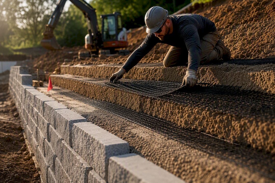
Geogrid is used behind retaining walls when the soil mass needs more reinforcement than the wall facing and gravity alone can provide. Wall height matters, but so do surcharge loads, backfill conditions, slopes above the wall, foundation soils, and drainage. Around the 4 foot range, many segmental retaining wall projects begin requiring additional design consideration, but there is no universal height where geogrid automatically becomes required. The wall system manufacturer, project specifications, local requirements, and engineer of record should ultimately determine the reinforcement layout.
TL;DR:
Geogrid is commonly used as retaining walls get taller or when surcharge, slopes, or difficult soil conditions increase the loads on the wall. The required reinforcement should come from the wall design rather than a height rule alone.
Proper geogrid selection should be based on long term design strength, product specific reduction factors, and the requirements of the engineered wall design rather than ultimate tensile strength alone.
Correct installation involves preparing a leveled base, tautly laying grid with appropriate embedment, and ensuring proper drainage to prevent hydrostatic pressure buildup.
Common failures stem from slack, wrong orientation, insufficient embedment, or poor drainage, emphasizing the importance of quality control and proper sequencing.
Engineered design may be required based on wall height, surcharge, slopes, soil conditions, drainage, and local requirements. Smaller walls should still follow the wall system manufacturer’s guidance.
Table of Contents
-
When Does a Retaining Wall Actually Require Geogrid Reinforcement?
-
How to Choose the Right Geogrid: Strength, Aperture, and Orientation
-
Contractor Checklist and Field Practices for Reinforced Walls
-
Maintenance and Inspection Guidelines for Geogrid-Reinforced Walls
-
Geogrid vs Geotextile, Soil Nails, and Tiebacks: Which Reinforcement Fits?
-
When to Hire an Engineer vs Relying on Manufacturer Guidance
What Is Retaining Wall Geogrid and How Does It Work?
Retaining wall geogrid is a polymer mesh embedded in compacted backfill behind a wall face, and it works by locking soil particles into its apertures while transferring tensile load through the reinforced mass back to the wall. That interlock is what separates a reinforced wall from a plain gravity wall stacked on hope. Engineers frame this as converting loose backfill into a coherent structural block, which is exactly how FHWA’s geosynthetics and MSE guidance describes reinforced soil systems and their design tables for reinforcement length and spacing.
Not all geogrid behaves the same way. The distinction that matters most for retaining walls:
-
Uniaxial geogrid has strength concentrated in one direction and is the standard choice for retaining walls, since load runs perpendicular to the wall face.
-
Biaxial geogrid distributes strength evenly in both directions and suits base stabilization under roads or slabs, not wall reinforcement.
-
Triaxial geogrid adds a third rib direction for extra load distribution, mostly seen in pavement and railway applications.
Material matters too. HDPE and PP geogrids are extruded and punched into a grid, giving high stiffness and good resistance to installation damage, while PET grids are often woven or knitted and prized for high tensile strength in taller walls. A review of polymer geogrid performance found these materials hold up well across decades of field use when specified and installed correctly.
When Does a Retaining Wall Actually Require Geogrid Reinforcement?
Height is the first filter, but it is far from the only one. Industry screening guidance generally breaks down like this:
-
Lower walls: Some segmental wall systems can perform as gravity walls when site conditions are favorable and manufacturer requirements are followed.
-
As wall height increases: Geogrid becomes increasingly common because the retained soil creates greater lateral load.
-
Walls with surcharge, backslope, weak foundation soils, or unusual loading: Reinforcement may be necessary even at relatively low wall heights.
Once a wall reaches the height or loading threshold requiring engineered design under the applicable code, project specifications, or wall system requirements, follow the engineer’s reinforcement layout rather than relying on a rule of thumb.
Beyond height, four conditions push a wall into reinforcement territory even below 4 feet. Surcharge loads (a driveway, patio, or parked vehicle sitting behind the wall) add pressure the blocks alone cannot resist. Weak or high plasticity backfill lacks the internal friction needed for a stable gravity mass. A slope rising above the wall crest increases the active soil pressure dramatically compared to level ground. Poor drainage lets hydrostatic pressure build behind the wall, a failure mode geogrid cannot fix on its own.
Engineers evaluate three stability modes when deciding grid length: global stability (does the whole slope stay put), external stability (does the reinforced mass resist sliding and overturning), and internal stability (does each grid layer hold its share of load without pulling out). Insufficient reinforcement length can reduce pullout resistance and compromise internal or overall wall stability.
How to Choose the Right Geogrid: Strength, Aperture, and Orientation
The single biggest mistake in DIY specification is buying geogrid based on ultimate tensile strength (UTS) alone. Manufacturers publish UTS as a lab number pulled under controlled tension, but engineers design with long-term design strength (LTDS), which knocks that number down using reduction factors for installation damage, creep under sustained load, and chemical or biological durability over the wall’s service life.
Engineers do not typically design from ultimate tensile strength alone. Long term design strength accounts for reduction factors such as creep, installation damage, and durability over the intended service life. Because those factors vary by product and application, use the manufacturer’s certified LTDS data for the specified geogrid.
When comparing products, ask your supplier for three things:
-
LTDS value, not just UTS, tied to your project’s expected service life.
-
Tensile test data per ASTM D6637, the standard method for geogrid strength testing, along with GRI-GG4 reduction factor guidance.
-
Aperture size matched to your backfill’s largest particle size, since apertures that are too small prevent proper soil interlock with coarse granular fill.
Orientation matters as much as strength. Uniaxial grids must run with their strong axis perpendicular to the wall face. Install one sideways and you have effectively installed no reinforcement at all, no matter how expensive the roll was.
Step-by-Step Geogrid Installation for Segmental Block Walls
Getting geogrid into the ground correctly is less about brute force and more about sequencing. Follow this order on a segmental block wall:
-
Prepare the leveling pad with compacted granular base, and plan your grid elevations before the first block goes down, spacing layers at roughly 16 to 24 inches vertically per common design guidance.
-
Place a full block course, then lay geogrid directly on top of that course, sandwiched under the next course. Never place grid on top of a finished wall face as an afterthought.
-
Pull the grid taut across its full width, free of wrinkles or folds, oriented with the strong axis running back into the slope.
-
Extend the geogrid to the length shown on the engineered or manufacturer approved wall design. Preliminary designs often use reinforcement lengths around 0.6 times wall height or greater, but surcharge, backslope, foundation conditions, and global stability can require substantially longer reinforcement.
-
Place and compact backfill in lifts that meet the wall system specifications and compaction requirements.
-
Use light compaction equipment near the wall face and keep heavy compaction equipment outside the setback required by the wall system. Excessive compaction force close to the face can push blocks out of alignment or introduce loads the wall was not designed to carry during construction.
-
Install drainage behind the reinforced zone: a perforated drain pipe at the base, a gravel chimney running vertically, and a geotextile fabric separating gravel from native soil.
Pro Tip: Grid tension matters more than most installers realize. A folded or slack layer loses a meaningful share of its pullout capacity before the wall ever sees a full load, so stretch and stake it before backfilling, not after.
Geogrid does not replace drainage. A wall can have perfect reinforcement and still fail from hydrostatic pressure if water has nowhere to go.
What Installation Mistakes Cause Geogrid Walls to Fail?
Most geogrid failures trace back to a handful of repeatable mistakes rather than product defects. Watch for these on any job site:
-
Slack or wrinkled grid that never develops full tension under load, cutting effective pullout resistance.
-
Wrong orientation, running the weak axis toward the slope instead of the strong axis.
-
Short embedment, where installers stop the grid early to save material and undermine internal stability.
-
Excess fines in backfill, which clog grid apertures and prevent the interlock the whole system depends on.
-
Skipped drainage, leaving no path for water to escape the reinforced zone.
On-site quality control should include measuring actual embedment length against the drawing, visually confirming the grid is flat and taut before backfill covers it, and logging compaction passes with density test results where the spec calls for them. A blog post from Barnhart Excavating on compaction and site documentation covers how these records protect both contractor and client if a dispute ever arises.
Contractor Checklist and Field Practices for Reinforced Walls
A reinforced wall project runs smoother when the paperwork is settled before the first block goes down. Before mobilizing equipment, confirm you have the engineer’s stamped drawings, written LTDS confirmation from the geogrid supplier, a roll-length and overlap plan that avoids mid-run splices, a drainage layout showing pipe and gravel chimney placement, compaction specs by lift thickness, and clear acceptance criteria for the inspector.
On-site sequencing matters just as much as the paperwork:
-
Establish a consistent compaction pattern working from the center of each lift outward toward the face.
-
Assign clear roles between the crew placing grid and the inspector verifying embedment and tension.
-
Halt work and call the engineer of record if soil conditions, groundwater, or slope geometry differ from what the drawings assumed.
Pro Tip: Photograph every grid layer before it gets buried, with a tape measure visible showing embedment length. That single habit resolves more disputes than any written report.
For reinforced wall construction, document grid placement before it is buried. Photos, reinforcement lengths, material identification, and applicable compaction test results create a useful record if questions come up later.
Maintenance and Inspection Guidelines for Geogrid-Reinforced Walls
A reinforced wall is not maintenance free just because the reinforcement is buried and out of sight. Inspect the wall face periodically and after any major rain event, looking for bulging, leaning, or rotation of individual blocks, which often signals reinforcement pullout or drainage failure rather than a cosmetic issue.
Check the drainage outlets at the base of the wall. A dry outlet after heavy rain is a warning sign, not a good one. It usually means the drain pipe has clogged with fines or the gravel chimney has silted in, both of which let hydrostatic pressure build behind the wall where geogrid alone cannot compensate for it.
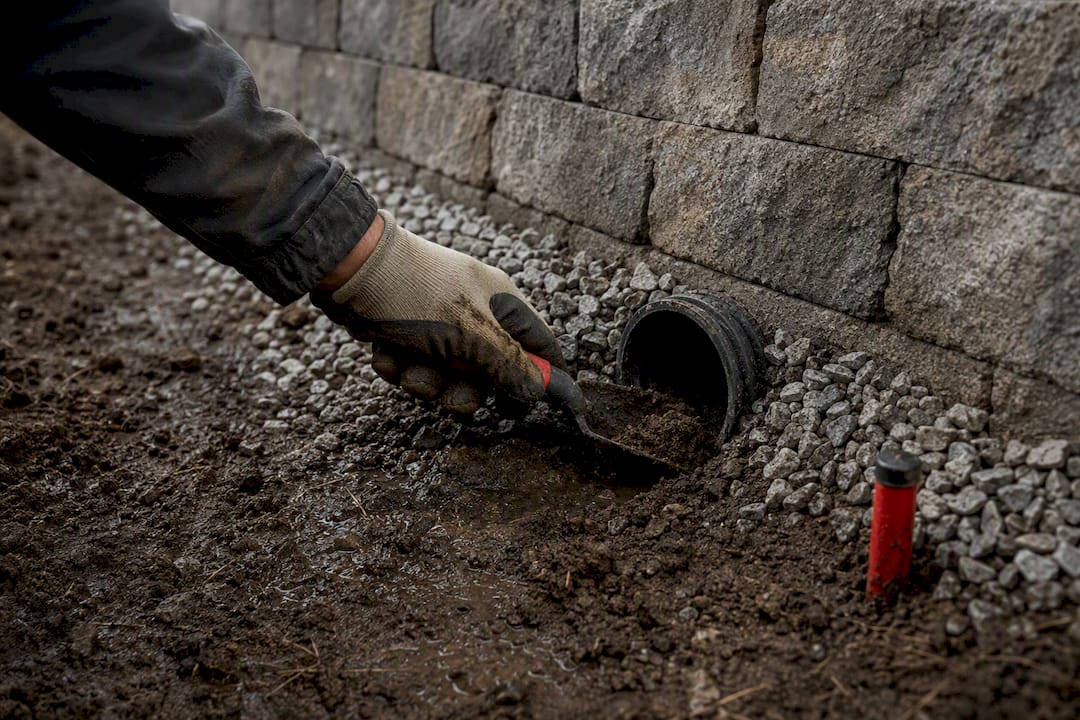
Watch for cracking or gapping at the top of the wall, especially near corners, which can indicate differential settlement in the reinforced soil mass. Vegetation growing directly out of the wall face, particularly woody plants, should be removed promptly since roots can work into joints and disrupt block alignment over time.
After construction, watch for movement at the wall face, settlement above the reinforced zone, blocked drainage outlets, erosion, or persistent water behind the wall. Any noticeable bulging, rotation, cracking, or settlement should be evaluated before the problem progresses. For engineered walls, follow the inspection and maintenance requirements established by the designer or owner.
Geogrid vs Geotextile, Soil Nails, and Tiebacks: Which Reinforcement Fits?
Geotextile and geogrid are not interchangeable terms. Many geotextiles used around retaining walls serve separation, filtration, or drainage functions, while geogrid is commonly selected for soil reinforcement because its open grid structure develops interlock with aggregate or backfill. High strength geotextiles can also be engineered as reinforcement, so the specified product and function matter.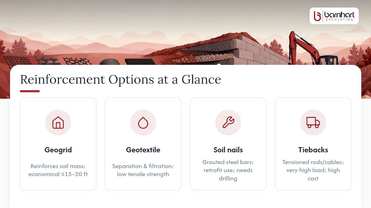
Soil nails are steel bars grouted into drilled holes behind an existing slope or wall face, typically used to stabilize a cut slope or retrofit an existing wall rather than build a new one from scratch. They work well where excavation space is tight and a new MSE mass is not practical, but they require drilling equipment and specialized installation crews that add cost quickly.
Tiebacks anchor a wall face to stable soil or rock farther back from the wall through a tensioned steel cable or rod, common in soldier pile and lagging walls or tall commercial retaining structures. They handle very high loads and tight footprints but come with a significantly higher engineering and construction cost than a geogrid-reinforced segmental wall.
For most residential and light commercial retaining walls under roughly 15 to 20 feet, geogrid remains the most economical structural solution because it uses the soil itself as the reinforcing mass rather than importing steel and drilling equipment. Soil nails and tiebacks earn their higher cost on tall walls, tight sites, or retrofit situations where a new reinforced soil mass simply is not feasible.
When to Hire an Engineer vs Relying on Manufacturer Guidance
Engineering requirements vary by jurisdiction, wall system, wall height, loading, and site conditions. Surcharge loads, steep slopes, poor foundation soils, drainage concerns, structures near the wall, or unusual geometry can trigger engineering even on relatively low walls. When the wall falls outside the manufacturer’s standard gravity wall conditions or local requirements call for engineered design, get the engineer involved before construction begins.
Where Retaining Wall Work Fits Into Site Development
Retaining walls do not exist separately from the rest of the site. Their performance depends heavily on excavation, subgrade conditions, drainage, backfill placement, compaction, and final grading.
Barnhart Excavating handles earthwork, grading, drainage infrastructure, utilities, stabilization, and other civil site work throughout Oklahoma. Our crews have also worked with geogrid in subgrade stabilization applications where soil conditions required reinforced aggregate sections.
When a site includes an engineered retaining wall, the wall contractor, civil or geotechnical engineer, and earthwork contractor need to coordinate elevations, excavation limits, drainage, backfill requirements, and surrounding site grades before construction begins.

Authoritative Standards and Guidance to Consult
For engineered specifications, start with FHWA’s MSE and geosynthetics guidance, ASTM D6637 for tensile testing, and GRI-GG4 for reduction factor calculations. Manufacturer design guides fill in product-specific installation details.
Sources
-
Polymer geogrids: review of material, design and structure relationships (PMC)
-
When Is Geogrid Required for Retaining Walls? Engineering Decision Guide
FAQ
Do I need geogrid for a 4-foot retaining wall?
Maybe. A 4 foot wall is often where additional design considerations come into play, but geogrid requirements depend on the wall system, surcharge loads, soil conditions, backslope, drainage, and local requirements. Follow the manufacturer’s guidance or engineered wall design rather than relying on height alone.
When should you use geogrid on a retaining wall?
Geogrid is commonly used as retaining walls get taller or when surcharge loads, slopes, weak soils, or other site conditions increase pressure on the wall. The required reinforcement should come from the wall system design rather than a universal height rule.
What is geogrid used for in retaining walls?
Geogrid reinforces the soil behind a wall, converting loose backfill into a mechanically stabilized earth mass that resists sliding and overturning far better than the wall blocks alone.
What site work is required around an engineered retaining wall?
Retaining wall construction has to be coordinated with excavation, foundation conditions, drainage, reinforced backfill, compaction, utilities, and final grades. Those surrounding conditions can be just as important to wall performance as the facing and geogrid themselves.